|
|
IMG_2512
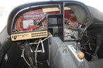
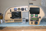
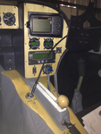
Did numerous test fit insertions of the instrument panel shell. I think I finally have it ready to install.
Date: 12/16/2011
Views: 3251
|
|
|
IMG_2537
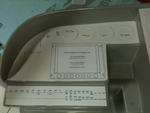
Here you can see the numerous check lists used in the inspections laid out on the wing.
Date: 03/02/2012
Views: 3212
|
|
|
|
IMG_2451
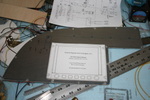
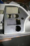
Templates were used to transfer the instrument locations to the aluminum panels for cutting.
Date: 10/24/2011
Views: 4392
|
|
|
IMG_2509
and 60 Kts on the airspeed (also a bit less)
Date: 02/28/2012
Views: 3019
|
|
|
|
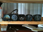
IMG_2470
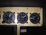
Another test fit. Getting better. Still waiting on the electroluminescent light ring for the altimeter.
Date: 11/13/2011
Views: 3176
|
|
|
IMG_2559
Add the 2 meter extension to the 1 meter length and run the viewer down to the brake area.
Date: 03/12/2012
Views: 3727
|
|
|
|
IMG_2555
Now you can observe the reservoir from below the aircraft where you control the run of fluid into the brake.
Date: 03/12/2012
Views: 3374
|
|
|
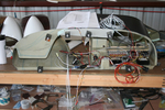
IMG_2523
But I'm still piddling around with the wiring and cabling. Found out today that the GRT Sport SX will control a Garmin SL30 radio and the Microair 760 will support SL30 type input/output. So, I'm working on adding the necessary wiring between the two.
Date: 01/03/2012
Views: 2833
|
|
|
|
IMG_2517
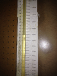
This is 160 Kts on the manometer (right on)
Date: 02/28/2012
Views: 2979
|
|
|
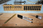
IMG_2460
Used our hydraulic punch to poke out the round holes. The rectangular holes were corner drilled and cut out with aircraft shears. Files were used to clean up the holes in shape and size.
Date: 10/27/2011
Views: 6426
|
|
|
|
IMG_2582
Brought the pitot/static manometer out to test the P/S system.
Date: 02/27/2012
Views: 2915
|
|
|
IMG_2538
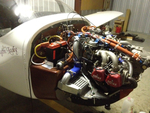
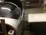
Uncowled engine open for inspection of all the wiring and plumbing and physical connections.
Date: 03/02/2012
Views: 3269
|
|
|
|
IMG_2571
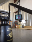
The nasty job of bleeding brakes. How do you do it without assistance? You get out the inspection camera and point the camera head at the brake reservoir.
Date: 03/12/2012
Views: 3594
|
|
|
IMG_2463
Here's why the bottom breakers are upside down. It puts the buss bars connecting the inputs together. The first breaker in the bottom row is the main output from the alternator so it is right side up so the output goes to the buss bars.
Date: 10/28/2011
Views: 4079
|
|
|
|
IMG_2309
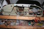
The obvious place to begin weight reduction was the ridiculously heavy instrument panel. Removed it and put the Garmin radios, etc. up for sale. Meanwhile, I began to lay out the instrument configuration in the old panel.
Date: 10/06/2011
Views: 6038
|
|
|
IMG_2454
I had some maple veneer from another project which came in handy to cover the sheet aluminum plates. I think it's much more attractive than painted aluminum.
Date: 10/24/2011
Views: 3628
|
|
|
|
IMG_2490
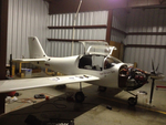
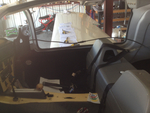
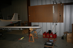
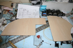
2012 Annual Condition Inspection. Opened it up and pulled the wings.
Date: 02/24/2012
Views: 2595
|
|
|
IMG_2525
Wiring in the instrument panel. From a couple weeks ago, not the final iteration.
Date: 01/14/2012
Views: 2898
|
|
|
|
IMG_2125
These 8 lbs of instruments were removed from the old panel along with the approximately 35 lbs of Garmin H/W.
Date: 11/24/2011
Views: 3138
|
|
|
IMG_2462
Here is the switch & breaker panel all nicely assembled. Don't know if you can tell, but the bottom row of breakers (except for the first one) are all upside down.
Date: 10/28/2011
Views: 3719
|
|