|
|
IMG_7285
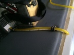
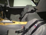
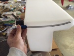
The new sight gage running up the back rest. 2 P-clips hold it in place. The new sight gage is also back lit with a strip of LED lights.
Date: 02/13/2014
Views: 5137
|
|
|
IMG_6843
Back from KOSH, I get out my video snake and try to run it down into the tank to find the leak.
Date: 10/01/2013
Views: 4896
|
|
|
|
IMG_7027
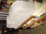
The underside of the fuel tank is covered in plastic wrap which will prevent the tank from bonding to the epoxy in the micro.
Date: 10/30/2013
Views: 5089
|
|
|
IMG_7230
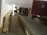
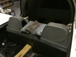
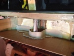
It was determined that a 1/4 in (6.4 mm) thick piece of rigid urethane foam topped with cork was needed to support the front "ledge" of the tank so it wouldn't sag.
Date: 01/26/2014
Views: 6493
|
|
|
|
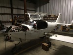
IMG_7738
Everything pretty much back together. Eight months work at this point.
Date: 05/10/2014
Views: 9282
|
|
|
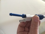
IMG_7315
The starboard side outlet installed. Fuel outlet to the fuel selector is on the port side and fuel return from the engine is on the starboard side.
Date: 02/17/2014
Views: 5708
|
|
|
|
IMG_6960
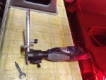
The rotary tool that did most of the cutting. Front and rear sides of the back rest.
Date: 10/17/2013
Views: 4970
|
|
|
IMG_6995
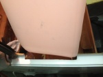
The cutout in the passenger door sill now allows entry of the tank.
Date: 10/21/2013
Views: 7588
|
|
|
|
IMG_6973
In this view fore is down, aft is up, port to the right and starboard to the left.
Date: 10/18/2013
Views: 4785
|
|
|
IMG_7282
Two venting outlets.
Date: 02/13/2014
Views: 5683
|
|
|
|
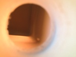
IMG_6855
But I can't get it past the entrance to the tank. Looks like I'll have to tear into things.
Date: 10/01/2013
Views: 5317
|
|
|
IMG_6960 1
One needs some room near the cockpit so the wings come off. In addition, all the connections to the fuel tank were removed.
Date: 11/10/2013
Views: 5130
|
|
|
|
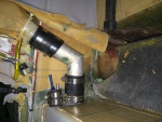
IMG_7281
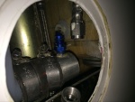
This picture illustrates how the new vent will be installed to obtain the best venting possible within the limits of the tank.
Date: 02/13/2014
Views: 5710
|
|
|
IMG_7735
Not as nice as it was but still not looking too shabby.
Date: 05/10/2014
Views: 6416
|
|
|
|
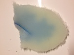
IMG_6973_em_sa
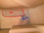
Here I have annotated the important elements. The red outlines the fiberglass support bonded to the bottom of the tank. Blue arrow points to the blue crack. The crack formed exactly as a stress analysis says it should, at 45º to the corner of that supp
Date: 10/18/2013
Views: 4394
|
|
|
IMG_7730
Returned the upholstery on to the back.
Date: 05/09/2014
Views: 7003
|
|
|
|
IMG_6978
The crack as viewed from the top side.
Date: 10/19/2013
Views: 5104
|
|
|
IMG_6976
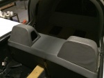
At this point all that's left is that portion of the tank which was bonded to the back of the back rest.
Date: 10/19/2013
Views: 4850
|
|
|
|
IMG_7313
The filler neck and vent installed in the tank.
Date: 02/17/2014
Views: 5726
|
|
|
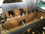
IMG_7233
2-ply fiberglass strips were made up to be bonded to the inside of the unit. These strips went on all 4 sides. Here the strip is being bonded to the aft wall.
Date: 01/26/2014
Views: 6510
|
|