|
|
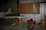
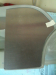
IMG_2582
Brought the pitot/static manometer out to test the P/S system.
Date: 02/27/2012
Views: 3410
|
|
|
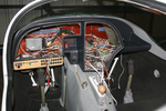
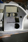
IMG_2309
The obvious place to begin weight reduction was the ridiculously heavy instrument panel. Removed it and put the Garmin radios, etc. up for sale. Meanwhile, I began to lay out the instrument configuration in the old panel.
Date: 10/06/2011
Views: 7041
|
|
|
|
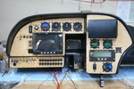
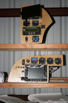
IMG_2502
Just the instruments. The wiring of everything in back will be the next big project.
Date: 11/23/2011
Views: 3481
|
|
|
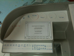
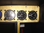
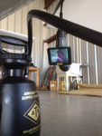
IMG_2517
This is 160 Kts on the manometer (right on)
Date: 02/28/2012
Views: 3449
|
|
|
|
IMG_2518
And 140 Kts on the airspeed (right on)
Date: 02/28/2012
Views: 3829
|
|
|
IMG_2463
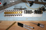
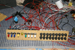
Here's why the bottom breakers are upside down. It puts the buss bars connecting the inputs together. The first breaker in the bottom row is the main output from the alternator so it is right side up so the output goes to the buss bars.
Date: 10/28/2011
Views: 4550
|
|
|
|
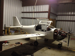
IMG_2571
Opened all the inspection holes to ensure all is well inside.
Date: 02/24/2012
Views: 3639
|
|
|
IMG_2528
View from the other side. Must have down 5 test fit by the last one. Each resulted in finding things to correct. So I've been correcting things for a couple weeks now. More wire labels, adding connectors, checking pinouts, testing switches, finding is
Date: 01/14/2012
Views: 3431
|
|
|
|
IMG_2312
This was the more difficult fit of the three.
Date: 10/06/2011
Views: 7577
|
|
|
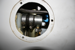
IMG_2555
Now you can observe the reservoir from below the aircraft where you control the run of fluid into the brake.
Date: 03/12/2012
Views: 3899
|
|
|
|
IMG_2508
Tested every 20 kts from 40 Kts to 180 Kts. Here's 60 Kts on the manometer (actually a bit less)
Date: 02/28/2012
Views: 3280
|
|
|
IMG_2460
Used our hydraulic punch to poke out the round holes. The rectangular holes were corner drilled and cut out with aircraft shears. Files were used to clean up the holes in shape and size.
Date: 10/27/2011
Views: 7082
|
|
|
|
IMG_2524
Maybe by the end of the week I can have the shell installed and wired into the aircraft so I can plug these into it. We'll see. These 26ºF (-3.3ºC) mornings have been limiting me to only 4 or 5 hours of afternoon work a day.
Date: 01/03/2012
Views: 3531
|
|
|
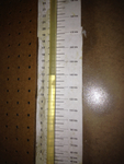
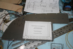
IMG_2537
Here you can see the numerous check lists used in the inspections laid out on the wing.
Date: 03/02/2012
Views: 3722
|
|
|
|
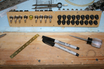
IMG_2468
Wiring begins in earnest. Color coding has been added to the switches. Red-Master, Blue-Ignition, Yellow-Starter, Green-Boost Pump & White-Lighting.
Date: 11/13/2011
Views: 3753
|
|
|
IMG_2451
Templates were used to transfer the instrument locations to the aluminum panels for cutting.
Date: 10/24/2011
Views: 4925
|
|
|
|
IMG_2462
Here is the switch & breaker panel all nicely assembled. Don't know if you can tell, but the bottom row of breakers (except for the first one) are all upside down.
Date: 10/28/2011
Views: 4207
|
|
|
IMG_2437
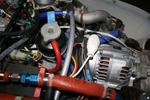
Eventually, the 2nd alternator and supporting H/W will go. Also, I have Parahelion copper-clad aluminum fat wire which will replace the existing fat wire.
Date: 10/15/2011
Views: 3579
|
|
|
|
IMG_2490
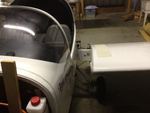
2012 Annual Condition Inspection. Opened it up and pulled the wings.
Date: 02/24/2012
Views: 3096
|
|
|
IMG_2456
Drilling for the rivets to hold the anchor nuts required novel technique. Eventually, all anchor nuts were installed.
Date: 10/25/2011
Views: 4589
|
|