|
|
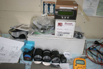
IMG_2123
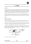
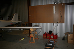
And then another 7 lbs of alternator H/W and about 4 lbs of Whelen strobe/lights/power supply. That sleek piece in the lower left is one of the 6 oz AEROLED Nav/Strobe units replacing the Whelens.
Date: 11/24/2011
Views: 3694
|
|
|
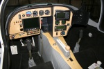
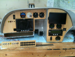
IMG_2502
Just the instruments. The wiring of everything in back will be the next big project.
Date: 11/23/2011
Views: 3495
|
|
|
|
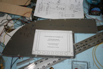
IMG_2307
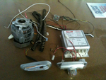
Cardboard cutouts and templates were used to shape and size the panels and to decide where instruments should go.
Date: 10/06/2011
Views: 4664
|
|
|
IMG_2456
Drilling for the rivets to hold the anchor nuts required novel technique. Eventually, all anchor nuts were installed.
Date: 10/25/2011
Views: 4611
|
|
|
|
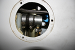
IMG_2571
Opened all the inspection holes to ensure all is well inside.
Date: 02/24/2012
Views: 3657
|
|
|
IMG_2565
You can see the bubbles of air coming from the brake line as you push fluid in from below. You can also manipulate the brake master to assist the flow of air out of the system.
Date: 03/12/2012
Views: 6092
|
|
|
|
IMG_2491
Other wing. I'll only show a few of the pics from the annual.
Date: 02/24/2012
Views: 3507
|
|
|
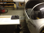
IMG_2551
Today I installed the new cover for the console and began work on the brake plumbing. I need to replace the line from the reservoir to the master as it interferes with the trim switch. Replacement parts now on order.
Date: 02/21/2012
Views: 3232
|
|
|
|
IMG_2452
The Garmin equipment sold very quickly and the proceeds were used to buy the new instruments. Here are the 2 1/2" "backup" gauges with the Microair Comm & Xponder as well as the GRT EIS 4000 from the old panel. At this point I was sti
Date: 10/24/2011
Views: 5275
|
|
|
IMG_2554
After a preliminary W&B done last week, the CG was now somewhat aft. After all, I had removed almost 40 lbs (18 Kilos) from the instrument panel and another 7 lbs (3 kilos) from the engine compartment. So I pulled the battery from below the baggage
Date: 02/21/2012
Views: 3298
|
|
|
|
IMG_2451
Templates were used to transfer the instrument locations to the aluminum panels for cutting.
Date: 10/24/2011
Views: 4954
|
|
|
IMG_2065
The GRT Sport has arrived and almost all the instruments have been set in their panels. This is a test fit. It was necessary to adjust the big opening in the main for clearance of some of the various instruments.
Date: 11/05/2011
Views: 6001
|
|
|
|
IMG_2468
Wiring begins in earnest. Color coding has been added to the switches. Red-Master, Blue-Ignition, Yellow-Starter, Green-Boost Pump & White-Lighting.
Date: 11/13/2011
Views: 3762
|
|
|
IMG_2528
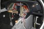
View from the other side. Must have down 5 test fit by the last one. Each resulted in finding things to correct. So I've been correcting things for a couple weeks now. More wire labels, adding connectors, checking pinouts, testing switches, finding is
Date: 01/14/2012
Views: 3453
|
|
|
|
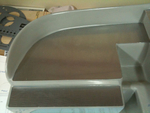
IMG_2313
Panel plates were cut from aluminum and fitted to the fiberglass.
Date: 10/06/2011
Views: 5563
|
|
|
IMG_2513
Had to make up a new cover plate for the back of the transmission where alternator #2 formerly resided.
Date: 12/16/2011
Views: 3183
|
|
|
|
IMG_2582
Brought the pitot/static manometer out to test the P/S system.
Date: 02/27/2012
Views: 3425
|
|
|
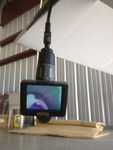
IMG_2559
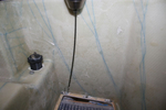
Add the 2 meter extension to the 1 meter length and run the viewer down to the brake area.
Date: 03/12/2012
Views: 4278
|
|
|
|
IMG_2509
and 60 Kts on the airspeed (also a bit less)
Date: 02/28/2012
Views: 3595
|
|
|
IMG_2526
Again a picture from a couple weeks ago. One of the initial test fit of the panel and check of wiring runs.
Date: 01/14/2012
Views: 3424
|
|