|
|
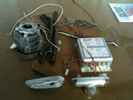
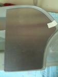
IMG_2123
And then another 7 lbs of alternator H/W and about 4 lbs of Whelen strobe/lights/power supply. That sleek piece in the lower left is one of the 6 oz AEROLED Nav/Strobe units replacing the Whelens.
Date: 11/24/2011
Views: 3610
|
|
|
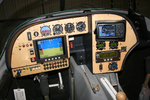
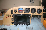
IMG_2545
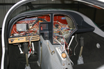
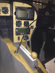
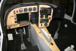
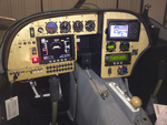
Here's a decent picture of the new panel all lit up. As far as I can tell, everything works now. I still need to set up the GRT Sport SX, MicroAir 760 Radio and MicroAir T2000 Transponder.
Date: 02/20/2012
Views: 3374
|
|
|
|
IMG_2491
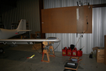
Other wing. I'll only show a few of the pics from the annual.
Date: 02/24/2012
Views: 3418
|
|
|
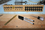
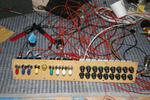
IMG_2462
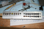
Here is the switch & breaker panel all nicely assembled. Don't know if you can tell, but the bottom row of breakers (except for the first one) are all upside down.
Date: 10/28/2011
Views: 4158
|
|
|
|
IMG_2518
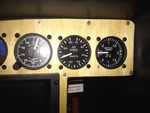
And 140 Kts on the airspeed (right on)
Date: 02/28/2012
Views: 3785
|
|
|
IMG_2528
View from the other side. Must have down 5 test fit by the last one. Each resulted in finding things to correct. So I've been correcting things for a couple weeks now. More wire labels, adding connectors, checking pinouts, testing switches, finding is
Date: 01/14/2012
Views: 3354
|
|
|
|
IMG_2522
Spent several weeks identifying and relabeling aircraft wiring. Talk about tedious...
Date: 01/03/2012
Views: 3355
|
|
|
IMG_2463
Here's why the bottom breakers are upside down. It puts the buss bars connecting the inputs together. The first breaker in the bottom row is the main output from the alternator so it is right side up so the output goes to the buss bars.
Date: 10/28/2011
Views: 4490
|
|
|
|
IMG_2447
Started to make up the switch and breaker panel.
Date: 10/24/2011
Views: 5366
|
|
|
IMG_2571
The nasty job of bleeding brakes. How do you do it without assistance? You get out the inspection camera and point the camera head at the brake reservoir.
Date: 03/12/2012
Views: 4143
|
|
|
|
IMG_2451
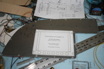
Templates were used to transfer the instrument locations to the aluminum panels for cutting.
Date: 10/24/2011
Views: 4860
|
|
|
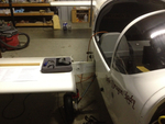
IMG_2551
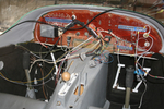
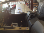
Today I installed the new cover for the console and began work on the brake plumbing. I need to replace the line from the reservoir to the master as it interferes with the trim switch. Replacement parts now on order.
Date: 02/21/2012
Views: 3145
|
|
|
|
IMG_2559
Add the 2 meter extension to the 1 meter length and run the viewer down to the brake area.
Date: 03/12/2012
Views: 4204
|
|
|
IMG_2468
Wiring begins in earnest. Color coding has been added to the switches. Red-Master, Blue-Ignition, Yellow-Starter, Green-Boost Pump & White-Lighting.
Date: 11/13/2011
Views: 3715
|
|
|
|
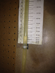
IMG_2582
Brought the pitot/static manometer out to test the P/S system.
Date: 02/27/2012
Views: 3364
|
|
|
IMG_2307
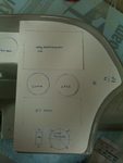
Cardboard cutouts and templates were used to shape and size the panels and to decide where instruments should go.
Date: 10/06/2011
Views: 4583
|
|
|
|
IMG_2456 1
This is a picture from the first big "smoke test."
Date: 02/10/2012
Views: 3290
|
|
|
IMG_2312
This was the more difficult fit of the three.
Date: 10/06/2011
Views: 7474
|
|
|
|
IMG_2490
Altimeter has been installed. Added a USB port for the GRT Sport. Began the label process.
Date: 11/22/2011
Views: 3682
|
|
|
IMG_2508
Tested every 20 kts from 40 Kts to 180 Kts. Here's 60 Kts on the manometer (actually a bit less)
Date: 02/28/2012
Views: 3236
|
|