|
|
IMG_2456 1
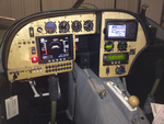
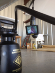
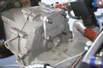
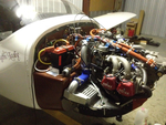
This is a picture from the first big "smoke test."
Date: 02/10/2012
Views: 3412
|
|
|
IMG_2571
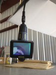
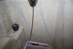
The nasty job of bleeding brakes. How do you do it without assistance? You get out the inspection camera and point the camera head at the brake reservoir.
Date: 03/12/2012
Views: 4390
|
|
|
|
IMG_2565
You can see the bubbles of air coming from the brake line as you push fluid in from below. You can also manipulate the brake master to assist the flow of air out of the system.
Date: 03/12/2012
Views: 6303
|
|
|
IMG_2537
Here you can see the numerous check lists used in the inspections laid out on the wing.
Date: 03/02/2012
Views: 3827
|
|
|
|
IMG_2555
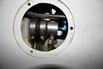
Now you can observe the reservoir from below the aircraft where you control the run of fluid into the brake.
Date: 03/12/2012
Views: 4012
|
|
|
IMG_2447
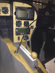
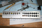
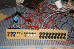
Started to make up the switch and breaker panel.
Date: 10/24/2011
Views: 5612
|
|
|
|
IMG_2559
Add the 2 meter extension to the 1 meter length and run the viewer down to the brake area.
Date: 03/12/2012
Views: 4390
|
|
|
IMG_2501
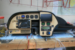
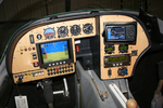
The full panel. Instrument final fit.
Date: 11/23/2011
Views: 4848
|
|
|
|
IMG_2508
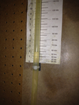
Tested every 20 kts from 40 Kts to 180 Kts. Here's 60 Kts on the manometer (actually a bit less)
Date: 02/28/2012
Views: 3369
|
|
|
IMG_2456
Drilling for the rivets to hold the anchor nuts required novel technique. Eventually, all anchor nuts were installed.
Date: 10/25/2011
Views: 4743
|
|
|
|
IMG_2545
Here's a decent picture of the new panel all lit up. As far as I can tell, everything works now. I still need to set up the GRT Sport SX, MicroAir 760 Radio and MicroAir T2000 Transponder.
Date: 02/20/2012
Views: 3558
|
|
|
IMG_2571
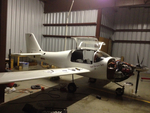
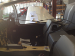
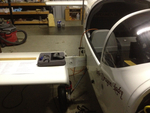
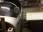
Opened all the inspection holes to ensure all is well inside.
Date: 02/24/2012
Views: 3749
|
|
|
|
IMG_2463
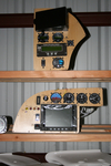
Here's why the bottom breakers are upside down. It puts the buss bars connecting the inputs together. The first breaker in the bottom row is the main output from the alternator so it is right side up so the output goes to the buss bars.
Date: 10/28/2011
Views: 4638
|
|
|
IMG_2513
Had to make up a new cover plate for the back of the transmission where alternator #2 formerly resided.
Date: 12/16/2011
Views: 3258
|
|
|
|
IMG_2491
Other wing. I'll only show a few of the pics from the annual.
Date: 02/24/2012
Views: 3613
|
|
|
IMG_2524
Maybe by the end of the week I can have the shell installed and wired into the aircraft so I can plug these into it. We'll see. These 26ºF (-3.3ºC) mornings have been limiting me to only 4 or 5 hours of afternoon work a day.
Date: 01/03/2012
Views: 3610
|
|
|
|
IMG_2123
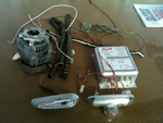
And then another 7 lbs of alternator H/W and about 4 lbs of Whelen strobe/lights/power supply. That sleek piece in the lower left is one of the 6 oz AEROLED Nav/Strobe units replacing the Whelens.
Date: 11/24/2011
Views: 3799
|
|
|
IMG_2538
Uncowled engine open for inspection of all the wiring and plumbing and physical connections.
Date: 03/02/2012
Views: 3774
|
|
|
|
IMG_2490
2012 Annual Condition Inspection. Opened it up and pulled the wings.
Date: 02/24/2012
Views: 3198
|
|
|
IMG_2468
Wiring begins in earnest. Color coding has been added to the switches. Red-Master, Blue-Ignition, Yellow-Starter, Green-Boost Pump & White-Lighting.
Date: 11/13/2011
Views: 3826
|
|