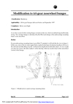
|
|
IMG_2551
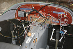
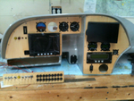
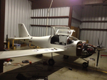
Today I installed the new cover for the console and began work on the brake plumbing. I need to replace the line from the reservoir to the master as it interferes with the trim switch. Replacement parts now on order.
Date: 02/21/2012
Views: 3122
|
|
|
IMG_2452
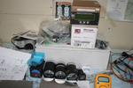
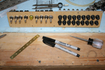
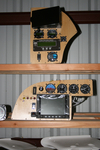
The Garmin equipment sold very quickly and the proceeds were used to buy the new instruments. Here are the 2 1/2" "backup" gauges with the Microair Comm & Xponder as well as the GRT EIS 4000 from the old panel. At this point I was sti
Date: 10/24/2011
Views: 5089
|
|
|
|
IMG_2554
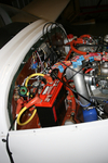
After a preliminary W&B done last week, the CG was now somewhat aft. After all, I had removed almost 40 lbs (18 Kilos) from the instrument panel and another 7 lbs (3 kilos) from the engine compartment. So I pulled the battery from below the baggage
Date: 02/21/2012
Views: 3195
|
|
|
IMG_2456
Drilling for the rivets to hold the anchor nuts required novel technique. Eventually, all anchor nuts were installed.
Date: 10/25/2011
Views: 4446
|
|
|
|
IMG_2517
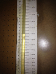
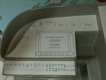
This is 160 Kts on the manometer (right on)
Date: 02/28/2012
Views: 3380
|
|
|
IMG_2523
But I'm still piddling around with the wiring and cabling. Found out today that the GRT Sport SX will control a Garmin SL30 radio and the Microair 760 will support SL30 type input/output. So, I'm working on adding the necessary wiring between the two.
Date: 01/03/2012
Views: 3191
|
|
|
|
IMG_2462
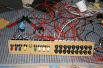
Here is the switch & breaker panel all nicely assembled. Don't know if you can tell, but the bottom row of breakers (except for the first one) are all upside down.
Date: 10/28/2011
Views: 4132
|
|
|
IMG_2522
Spent several weeks identifying and relabeling aircraft wiring. Talk about tedious...
Date: 01/03/2012
Views: 3333
|
|
|
|
IMG_2582
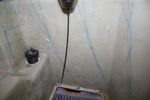
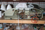
Brought the pitot/static manometer out to test the P/S system.
Date: 02/27/2012
Views: 3337
|
|
|
IMG_2437
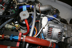
Eventually, the 2nd alternator and supporting H/W will go. Also, I have Parahelion copper-clad aluminum fat wire which will replace the existing fat wire.
Date: 10/15/2011
Views: 3490
|
|
|
|
IMG_2491
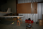
Other wing. I'll only show a few of the pics from the annual.
Date: 02/24/2012
Views: 3394
|
|
|
IMG_2065
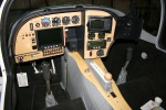
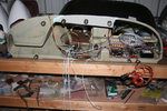
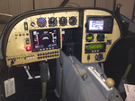
The GRT Sport has arrived and almost all the instruments have been set in their panels. This is a test fit. It was necessary to adjust the big opening in the main for clearance of some of the various instruments.
Date: 11/05/2011
Views: 5905
|
|
|
|
IMG_2468
Wiring begins in earnest. Color coding has been added to the switches. Red-Master, Blue-Ignition, Yellow-Starter, Green-Boost Pump & White-Lighting.
Date: 11/13/2011
Views: 3703
|
|
|
IMG_2447
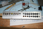
Started to make up the switch and breaker panel.
Date: 10/24/2011
Views: 5322
|
|
|
|
IMG_2525
Wiring in the instrument panel. From a couple weeks ago, not the final iteration.
Date: 01/14/2012
Views: 3215
|
|
|
IMG_2537
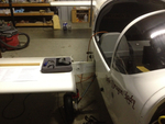
Here you can see the numerous check lists used in the inspections laid out on the wing.
Date: 03/02/2012
Views: 3646
|
|
|
|
IMG_2309
The obvious place to begin weight reduction was the ridiculously heavy instrument panel. Removed it and put the Garmin radios, etc. up for sale. Meanwhile, I began to lay out the instrument configuration in the old panel.
Date: 10/06/2011
Views: 6853
|
|
|
IMG_2463
Here's why the bottom breakers are upside down. It puts the buss bars connecting the inputs together. The first breaker in the bottom row is the main output from the alternator so it is right side up so the output goes to the buss bars.
Date: 10/28/2011
Views: 4471
|
|
|
|
IMG_2524
Maybe by the end of the week I can have the shell installed and wired into the aircraft so I can plug these into it. We'll see. These 26ºF (-3.3ºC) mornings have been limiting me to only 4 or 5 hours of afternoon work a day.
Date: 01/03/2012
Views: 3474
|
|
|
IMG_2456 1
This is a picture from the first big "smoke test."
Date: 02/10/2012
Views: 3275
|
|