|
|
IMG_2447
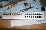
Started to make up the switch and breaker panel.
Date: 10/24/2011
Views: 5583
|
|
|
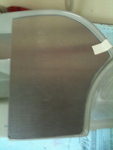
IMG_2509
and 60 Kts on the airspeed (also a bit less)
Date: 02/28/2012
Views: 3693
|
|
|
|
IMG_2526
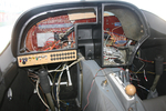
Again a picture from a couple weeks ago. One of the initial test fit of the panel and check of wiring runs.
Date: 01/14/2012
Views: 3486
|
|
|
IMG_2571
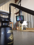
The nasty job of bleeding brakes. How do you do it without assistance? You get out the inspection camera and point the camera head at the brake reservoir.
Date: 03/12/2012
Views: 4361
|
|
|
|
IMG_2307
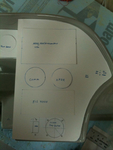
Cardboard cutouts and templates were used to shape and size the panels and to decide where instruments should go.
Date: 10/06/2011
Views: 4759
|
|
|
IMG_2555
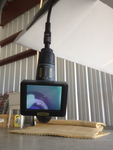
Now you can observe the reservoir from below the aircraft where you control the run of fluid into the brake.
Date: 03/12/2012
Views: 3999
|
|
|
|
IMG_2512
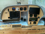
Did numerous test fit insertions of the instrument panel shell. I think I finally have it ready to install.
Date: 12/16/2011
Views: 3746
|
|
|
IMG_2522
Spent several weeks identifying and relabeling aircraft wiring. Talk about tedious...
Date: 01/03/2012
Views: 3482
|
|
|
|
IMG_2508
Tested every 20 kts from 40 Kts to 180 Kts. Here's 60 Kts on the manometer (actually a bit less)
Date: 02/28/2012
Views: 3354
|
|
|
IMG_2518
And 140 Kts on the airspeed (right on)
Date: 02/28/2012
Views: 3948
|
|
|
|
IMG_2463
Here's why the bottom breakers are upside down. It puts the buss bars connecting the inputs together. The first breaker in the bottom row is the main output from the alternator so it is right side up so the output goes to the buss bars.
Date: 10/28/2011
Views: 4627
|
|
|
IMG_2551
Today I installed the new cover for the console and began work on the brake plumbing. I need to replace the line from the reservoir to the master as it interferes with the trim switch. Replacement parts now on order.
Date: 02/21/2012
Views: 3314
|
|
|
|
IMG_2065
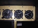
The GRT Sport has arrived and almost all the instruments have been set in their panels. This is a test fit. It was necessary to adjust the big opening in the main for clearance of some of the various instruments.
Date: 11/05/2011
Views: 6074
|
|
|
IMG_2582
Brought the pitot/static manometer out to test the P/S system.
Date: 02/27/2012
Views: 3484
|
|
|
|
IMG_2523
But I'm still piddling around with the wiring and cabling. Found out today that the GRT Sport SX will control a Garmin SL30 radio and the Microair 760 will support SL30 type input/output. So, I'm working on adding the necessary wiring between the two.
Date: 01/03/2012
Views: 3360
|
|
|
IMG_2565
You can see the bubbles of air coming from the brake line as you push fluid in from below. You can also manipulate the brake master to assist the flow of air out of the system.
Date: 03/12/2012
Views: 6272
|
|
|
|
IMG_2495
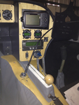
496 Mount, Microair Comm & Xponder, GRT EIS 4000, Fuel Pressure, Prop Controls.
Date: 11/22/2011
Views: 3894
|
|
|
IMG_2498
Switches and breakers have been labeled.
Date: 11/22/2011
Views: 3776
|
|
|
|
IMG_2454
I had some maple veneer from another project which came in handy to cover the sheet aluminum plates. I think it's much more attractive than painted aluminum.
Date: 10/24/2011
Views: 4122
|
|
|
IMG_2312
This was the more difficult fit of the three.
Date: 10/06/2011
Views: 7740
|
|