|
|
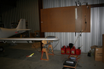
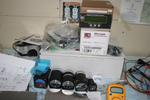
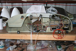
IMG_2582
Brought the pitot/static manometer out to test the P/S system.
Date: 02/27/2012
Views: 3422
|
|
|
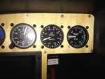
IMG_2518
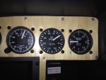
And 140 Kts on the airspeed (right on)
Date: 02/28/2012
Views: 3839
|
|
|
|
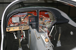
IMG_2309
The obvious place to begin weight reduction was the ridiculously heavy instrument panel. Removed it and put the Garmin radios, etc. up for sale. Meanwhile, I began to lay out the instrument configuration in the old panel.
Date: 10/06/2011
Views: 7067
|
|
|
IMG_2313
Panel plates were cut from aluminum and fitted to the fiberglass.
Date: 10/06/2011
Views: 5558
|
|
|
|
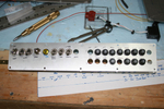
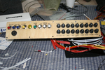
IMG_2447
Started to make up the switch and breaker panel.
Date: 10/24/2011
Views: 5455
|
|
|
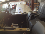
IMG_2571
Opened all the inspection holes to ensure all is well inside.
Date: 02/24/2012
Views: 3651
|
|
|
|
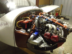
IMG_2538
Uncowled engine open for inspection of all the wiring and plumbing and physical connections.
Date: 03/02/2012
Views: 3710
|
|
|
IMG_2498
Switches and breakers have been labeled.
Date: 11/22/2011
Views: 3675
|
|
|
|
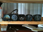
IMG_2452
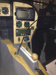
The Garmin equipment sold very quickly and the proceeds were used to buy the new instruments. Here are the 2 1/2" "backup" gauges with the Microair Comm & Xponder as well as the GRT EIS 4000 from the old panel. At this point I was sti
Date: 10/24/2011
Views: 5264
|
|
|
IMG_2559
Add the 2 meter extension to the 1 meter length and run the viewer down to the brake area.
Date: 03/12/2012
Views: 4270
|
|
|
|
IMG_2528
View from the other side. Must have down 5 test fit by the last one. Each resulted in finding things to correct. So I've been correcting things for a couple weeks now. More wire labels, adding connectors, checking pinouts, testing switches, finding is
Date: 01/14/2012
Views: 3447
|
|
|
IMG_2125
These 8 lbs of instruments were removed from the old panel along with the approximately 35 lbs of Garmin H/W.
Date: 11/24/2011
Views: 3680
|
|
|
|
IMG_2509
and 60 Kts on the airspeed (also a bit less)
Date: 02/28/2012
Views: 3591
|
|
|
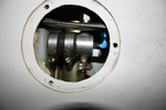
IMG_2571
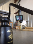
The nasty job of bleeding brakes. How do you do it without assistance? You get out the inspection camera and point the camera head at the brake reservoir.
Date: 03/12/2012
Views: 4229
|
|
|
|
IMG_2307
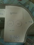
Cardboard cutouts and templates were used to shape and size the panels and to decide where instruments should go.
Date: 10/06/2011
Views: 4661
|
|
|
IMG_2123
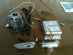
And then another 7 lbs of alternator H/W and about 4 lbs of Whelen strobe/lights/power supply. That sleek piece in the lower left is one of the 6 oz AEROLED Nav/Strobe units replacing the Whelens.
Date: 11/24/2011
Views: 3687
|
|
|
|
IMG_2525
Wiring in the instrument panel. From a couple weeks ago, not the final iteration.
Date: 01/14/2012
Views: 3281
|
|
|
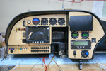
IMG_2502
Just the instruments. The wiring of everything in back will be the next big project.
Date: 11/23/2011
Views: 3489
|
|
|
|
IMG_2555
Now you can observe the reservoir from below the aircraft where you control the run of fluid into the brake.
Date: 03/12/2012
Views: 3913
|
|
|
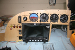
IMG_2490
Altimeter has been installed. Added a USB port for the GRT Sport. Began the label process.
Date: 11/22/2011
Views: 3750
|
|