|
|
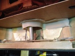
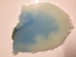
IMG_6977
The white stuff you see is low-expansion foam that was squirted in to provide support so this wouldn't happen. Unfortunately, I could not get foam under the port side sufficiently to support that side. That's where the crack developed.
Date: 10/19/2013
Views: 5257
|
|
|
IMG_7226
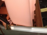
Here the urethane on the aluminum ledge has also been covered with cork. The cork both served to protect the tank and the urethane.
Date: 01/19/2014
Views: 5082
|
|
|
|
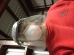
IMG_6966
Selfie of the protective gear needed. There was a LOT of fiberglass dust flying during the cutting.
Date: 10/17/2013
Views: 5080
|
|
|
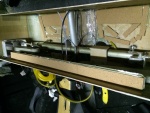
IMG_7230
It was determined that a 1/4 in (6.4 mm) thick piece of rigid urethane foam topped with cork was needed to support the front "ledge" of the tank so it wouldn't sag.
Date: 01/26/2014
Views: 6465
|
|
|
|
IMG_6975
The crack as viewed from the underside. it is about 1 5/8 in (4 cm) long and 1/32 in (1 mm) wide. Notice the blue staining on the underside surface.
Date: 10/19/2013
Views: 6422
|
|
|
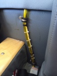
IMG_7767
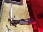
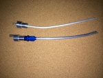
The sight gage with calibration markers.
Date: 05/18/2014
Views: 5905
|
|
|
|
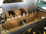
IMG_7233
2-ply fiberglass strips were made up to be bonded to the inside of the unit. These strips went on all 4 sides. Here the strip is being bonded to the aft wall.
Date: 01/26/2014
Views: 6477
|
|
|
IMG_7015
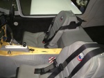
Finally, the new tank is in place. More or less.
Date: 10/23/2013
Views: 5460
|
|
|
|
IMG_6960
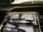
The rotary tool that did most of the cutting. Front and rear sides of the back rest.
Date: 10/17/2013
Views: 4950
|
|
|
IMG_7374
The filtering funnel keeps crap out of the fuel tank
Date: 02/22/2014
Views: 4368
|
|
|
|
IMG_6994
Seeing where the passenger door sill will have to be cut to allow the tank to go in.
Date: 10/21/2013
Views: 5600
|
|
|
IMG_6858
The old fittings as removed from the old tank. Vent on left, starboard outlet in the middle and port outlet on the right.
Date: 10/01/2013
Views: 6144
|
|
|
|
IMG_6962
Old 1/4 in (6.4 mm) vent on the top. Totally inadequate for the job. New 3/8 in (9.5 mm) vent on the bottom.
Date: 11/13/2013
Views: 5171
|
|
|
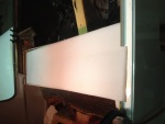
IMG_7319
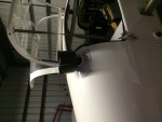
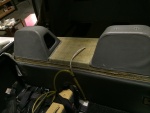
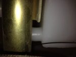
A test fit of the top. Check of the front.
Date: 02/17/2014
Views: 5109
|
|
|
|
IMG_7335
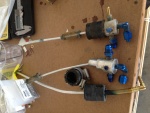
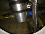
New sight gage connection clamped and fuel tight. The outlet to the fuel selector has been connected.
Date: 02/17/2014
Views: 6057
|
|
|
IMG_7738
Everything pretty much back together. Eight months work at this point.
Date: 05/10/2014
Views: 9249
|
|
|
|
IMG_7366
Applying the fiberglass/epoxy strips to the port side. Plastic wrap to prevent the epoxy from bonding to the tools used to hold the strip in place.
Date: 02/22/2014
Views: 6587
|
|
|
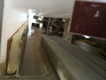
IMG_6996
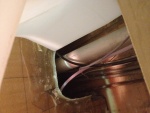
You also have to make sure you clear all the cables, plumbing and wiring in the "tunnel" area.
Date: 10/21/2013
Views: 5540
|
|
|
|
IMG_7536
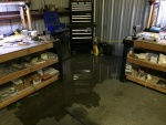
It was a pretty good flow of water for a while. Flooding the back of the hanger. No real damage as, from previous experience, I try to keep things off the hanger floor in any case.
Date: 03/20/2014
Views: 7238
|
|
|
IMG_7004
Here you see that the fuel outlets won't go past the pitch connection rod between the sticks. And this can not be removed to be replaced at a later date. The outlets have to be trimmed back by about 1/4 in (6.4 mm).
Date: 10/22/2013
Views: 6271
|
|