|
|
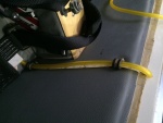
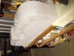
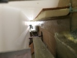
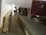
IMG_7285
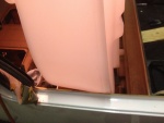
The new sight gage running up the back rest. 2 P-clips hold it in place. The new sight gage is also back lit with a strip of LED lights.
Date: 02/13/2014
Views: 4894
|
|
|
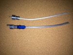
IMG_6962
Old 1/4 in (6.4 mm) vent on the top. Totally inadequate for the job. New 3/8 in (9.5 mm) vent on the bottom.
Date: 11/13/2013
Views: 4959
|
|
|
|
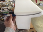
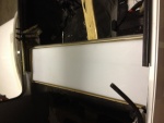
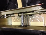
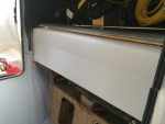
IMG_7281
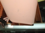
This picture illustrates how the new vent will be installed to obtain the best venting possible within the limits of the tank.
Date: 02/13/2014
Views: 5477
|
|
|
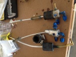
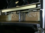
IMG_6858
The old fittings as removed from the old tank. Vent on left, starboard outlet in the middle and port outlet on the right.
Date: 10/01/2013
Views: 5927
|
|
|
|
IMG_7027
The underside of the fuel tank is covered in plastic wrap which will prevent the tank from bonding to the epoxy in the micro.
Date: 10/30/2013
Views: 4793
|
|
|
IMG_7030
The tank was then put in place so that the urethane and micro could shape themselves to the bottom of the tank
Date: 10/31/2013
Views: 4428
|
|
|
|
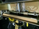
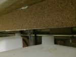
IMG_6956 1
With the tank removed, the micro and urethane could be covered with cork. The cork serves to protect the tank from abrasion by the support materials. You can also see the strip of urethane applied to the top of the aluminum support for the tank ledge.
Date: 11/10/2013
Views: 5259
|
|
|
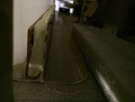
IMG_7226
Here the urethane on the aluminum ledge has also been covered with cork. The cork both served to protect the tank and the urethane.
Date: 01/19/2014
Views: 4815
|
|
|
|
IMG_7231
One final check to make sure everything fits and supports the tank.
Date: 01/26/2014
Views: 5112
|
|
|
IMG_7029
Supporting material in the form of rigid polyurethane sheet and micro/epoxy mix are laid out on the bottom of the fuselage.
Date: 10/31/2013
Views: 4711
|
|
|
|
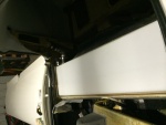
IMG_7312
With one final overall fit of the tank.
Date: 02/17/2014
Views: 7252
|
|
|
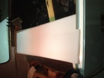
IMG_7015
Finally, the new tank is in place. More or less.
Date: 10/23/2013
Views: 5228
|
|
|
|
IMG_7230
It was determined that a 1/4 in (6.4 mm) thick piece of rigid urethane foam topped with cork was needed to support the front "ledge" of the tank so it wouldn't sag.
Date: 01/26/2014
Views: 6249
|
|
|
IMG_7232
Must have had the tank in/out two dozen times determining necessary clearances and supports.
Date: 01/26/2014
Views: 5185
|
|
|
|
IMG_7290
Bonded in the foam and cork support for the "ledge" at the front of the tank.
Date: 02/14/2014
Views: 4995
|
|
|
IMG_7305
Checked, double checked and again checked all the fits.
Date: 02/16/2014
Views: 5403
|
|
|
|
IMG_6994
Seeing where the passenger door sill will have to be cut to allow the tank to go in.
Date: 10/21/2013
Views: 5382
|
|
|
IMG_6995
The cutout in the passenger door sill now allows entry of the tank.
Date: 10/21/2013
Views: 7259
|
|
|
|
IMG_6996
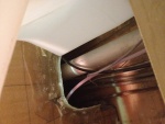
You also have to make sure you clear all the cables, plumbing and wiring in the "tunnel" area.
Date: 10/21/2013
Views: 5330
|
|
|
IMG_7004
Here you see that the fuel outlets won't go past the pitch connection rod between the sticks. And this can not be removed to be replaced at a later date. The outlets have to be trimmed back by about 1/4 in (6.4 mm).
Date: 10/22/2013
Views: 6034
|
|