|
|
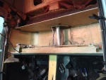
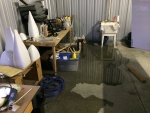
IMG_6982
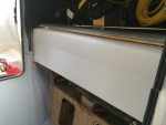
The tank must go into this space.
Date: 10/21/2013
Views: 12450
|
|
|
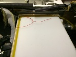
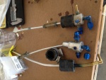
IMG_7365
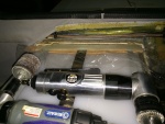
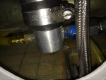
Getting the sight gage plumbing in place.
Date: 02/22/2014
Views: 12423
|
|
|
|
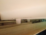
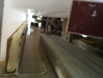
IMG_6989
In addition, the aileron tie rod between the sticks is in the way and will have to come out.
Date: 10/21/2013
Views: 12389
|
|
|
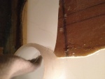
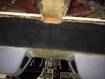
IMG_7014
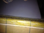
Next catch was where the filler needed to go into its' position. There was a piece blocking which had to be removed.
Date: 10/23/2013
Views: 12329
|
|
|
|
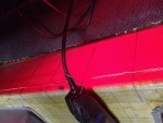
IMG_7535
Then we had a bit of drama as the sink developed a leak in the feed line.
Date: 03/20/2014
Views: 12209
|
|
|
IMG_7230
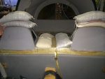
It was determined that a 1/4 in (6.4 mm) thick piece of rigid urethane foam topped with cork was needed to support the front "ledge" of the tank so it wouldn't sag.
Date: 01/26/2014
Views: 11520
|
|
|
|
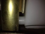
IMG_7567
Time to start putting upholstery back in place.
Date: 03/29/2014
Views: 11485
|
|
|
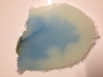
IMG_6975
The crack as viewed from the underside. it is about 1 5/8 in (4 cm) long and 1/32 in (1 mm) wide. Notice the blue staining on the underside surface.
Date: 10/19/2013
Views: 11308
|
|
|
|
IMG_6843
Back from KOSH, I get out my video snake and try to run it down into the tank to find the leak.
Date: 10/01/2013
Views: 11258
|
|
|
IMG_6858
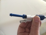
The old fittings as removed from the old tank. Vent on left, starboard outlet in the middle and port outlet on the right.
Date: 10/01/2013
Views: 11196
|
|
|
|
IMG_6962
The cut on the front side
Date: 10/17/2013
Views: 11043
|
|
|
IMG_7004
Here you see that the fuel outlets won't go past the pitch connection rod between the sticks. And this can not be removed to be replaced at a later date. The outlets have to be trimmed back by about 1/4 in (6.4 mm).
Date: 10/22/2013
Views: 11031
|
|
|
|
IMG_7367
Applying the fiberglass/epoxy strips to the starboard side.
Date: 02/22/2014
Views: 11013
|
|
|
IMG_7232
Must have had the tank in/out two dozen times determining necessary clearances and supports.
Date: 01/26/2014
Views: 10951
|
|
|
|
IMG_6961
The cut on the real side
Date: 10/17/2013
Views: 10857
|
|
|
IMG_7393
Shot bags (25 lbs each) to hold the top in place for the final bonding. 2 plies of fiberglass over a micro filler in the cut.
Date: 03/01/2014
Views: 10774
|
|
|
|
IMG_7335
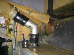
New sight gage connection clamped and fuel tight. The outlet to the fuel selector has been connected.
Date: 02/17/2014
Views: 10747
|
|
|
IMG_7282
Two venting outlets.
Date: 02/13/2014
Views: 10735
|
|
|
|
IMG_7313
The filler neck and vent installed in the tank.
Date: 02/17/2014
Views: 10690
|
|
|
IMG_7382
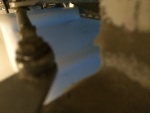
Blue fuel in the tank.
Date: 02/23/2014
Views: 10662
|
|