|
|
IMG_7430
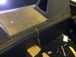
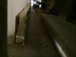
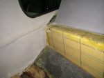
The front has bonded nicely around the sight gage entry.
Date: 03/11/2014
Views: 10291
|
|
|
IMG_6975
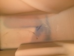
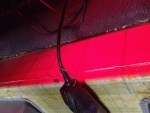
The crack as viewed from the underside. it is about 1 5/8 in (4 cm) long and 1/32 in (1 mm) wide. Notice the blue staining on the underside surface.
Date: 10/19/2013
Views: 11552
|
|
|
|
IMG_7373
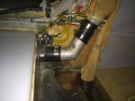
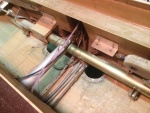
The vent system with all vent lines from the fuel sight gage and tank vents connected to the aircraft filler vent system.
Date: 02/22/2014
Views: 10811
|
|
|
IMG_7231
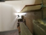
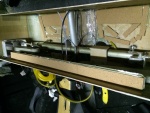
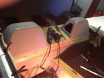
One final check to make sure everything fits and supports the tank.
Date: 01/26/2014
Views: 10049
|
|
|
|
IMG_7233
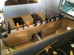
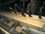
2-ply fiberglass strips were made up to be bonded to the inside of the unit. These strips went on all 4 sides. Here the strip is being bonded to the aft wall.
Date: 01/26/2014
Views: 12768
|
|
|
IMG_7315
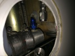
The starboard side outlet installed. Fuel outlet to the fuel selector is on the port side and fuel return from the engine is on the starboard side.
Date: 02/17/2014
Views: 10411
|
|
|
|
IMG_7226
Here the urethane on the aluminum ledge has also been covered with cork. The cork both served to protect the tank and the urethane.
Date: 01/19/2014
Views: 10346
|
|
|
IMG_7005
The space with the aileron tie rod and starboard side support removed.
Date: 10/22/2013
Views: 10670
|
|
|
|
IMG_7235
A strip being bonded to the front wall.
Date: 01/31/2014
Views: 10407
|
|
|
IMG_7305
Checked, double checked and again checked all the fits.
Date: 02/16/2014
Views: 10694
|
|
|
|
IMG_7568
And reconnecting the aileron tie rods.
Date: 03/29/2014
Views: 13028
|
|
|
IMG_7535
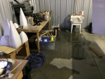
Then we had a bit of drama as the sink developed a leak in the feed line.
Date: 03/20/2014
Views: 12468
|
|
|
|
IMG_6957
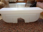
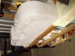
Front side of the new tank.
Date: 10/17/2013
Views: 10233
|
|
|
IMG_7322
Checking the back.
Date: 02/17/2014
Views: 12985
|
|
|
|
IMG_6958
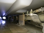
Tear out the interior to gain access to the upper part of the back where the fuel tank resides.
Date: 10/17/2013
Views: 10840
|
|
|
IMG_6973
In this view fore is down, aft is up, port to the right and starboard to the left.
Date: 10/18/2013
Views: 10211
|
|
|
|
IMG_7027
The underside of the fuel tank is covered in plastic wrap which will prevent the tank from bonding to the epoxy in the micro.
Date: 10/30/2013
Views: 10214
|
|
|
IMG_6962
The cut on the front side
Date: 10/17/2013
Views: 11281
|
|
|
|
IMG_6962
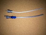
Old 1/4 in (6.4 mm) vent on the top. Totally inadequate for the job. New 3/8 in (9.5 mm) vent on the bottom.
Date: 11/13/2013
Views: 10059
|
|
|
IMG_6843
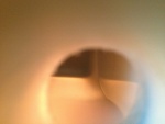
Back from KOSH, I get out my video snake and try to run it down into the tank to find the leak.
Date: 10/01/2013
Views: 11484
|
|