|
|
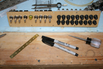
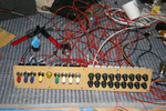
IMG_2462
Here is the switch & breaker panel all nicely assembled. Don't know if you can tell, but the bottom row of breakers (except for the first one) are all upside down.
Date: 10/28/2011
Views: 5827
|
|
|
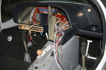
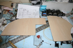
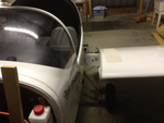
IMG_2528
View from the other side. Must have down 5 test fit by the last one. Each resulted in finding things to correct. So I've been correcting things for a couple weeks now. More wire labels, adding connectors, checking pinouts, testing switches, finding is
Date: 01/14/2012
Views: 5800
|
|
|
|
IMG_2555
Now you can observe the reservoir from below the aircraft where you control the run of fluid into the brake.
Date: 03/12/2012
Views: 5737
|
|
|
IMG_2526
Again a picture from a couple weeks ago. One of the initial test fit of the panel and check of wiring runs.
Date: 01/14/2012
Views: 5580
|
|
|
|
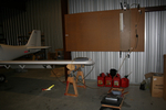
IMG_2537
Here you can see the numerous check lists used in the inspections laid out on the wing.
Date: 03/02/2012
Views: 5580
|
|
|
IMG_2454
I had some maple veneer from another project which came in handy to cover the sheet aluminum plates. I think it's much more attractive than painted aluminum.
Date: 10/24/2011
Views: 5491
|
|
|
|
IMG_2517
This is 160 Kts on the manometer (right on)
Date: 02/28/2012
Views: 5465
|
|
|
IMG_2551
Today I installed the new cover for the console and began work on the brake plumbing. I need to replace the line from the reservoir to the master as it interferes with the trim switch. Replacement parts now on order.
Date: 02/21/2012
Views: 5447
|
|
|
|
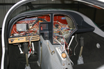
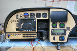
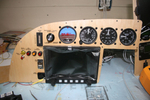
IMG_2502
Just the instruments. The wiring of everything in back will be the next big project.
Date: 11/23/2011
Views: 5407
|
|
|
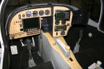
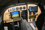
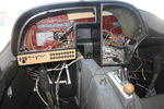
IMG_2545
Here's a decent picture of the new panel all lit up. As far as I can tell, everything works now. I still need to set up the GRT Sport SX, MicroAir 760 Radio and MicroAir T2000 Transponder.
Date: 02/20/2012
Views: 5397
|
|
|
|
IMG_2513
Had to make up a new cover plate for the back of the transmission where alternator #2 formerly resided.
Date: 12/16/2011
Views: 5385
|
|
|
IMG_2468
Wiring begins in earnest. Color coding has been added to the switches. Red-Master, Blue-Ignition, Yellow-Starter, Green-Boost Pump & White-Lighting.
Date: 11/13/2011
Views: 5371
|
|
|
|
IMG_2490
2012 Annual Condition Inspection. Opened it up and pulled the wings.
Date: 02/24/2012
Views: 5370
|
|
|
IMG_2512
Did numerous test fit insertions of the instrument panel shell. I think I finally have it ready to install.
Date: 12/16/2011
Views: 5368
|
|
|
|
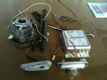
IMG_2123
And then another 7 lbs of alternator H/W and about 4 lbs of Whelen strobe/lights/power supply. That sleek piece in the lower left is one of the 6 oz AEROLED Nav/Strobe units replacing the Whelens.
Date: 11/24/2011
Views: 5367
|
|
|
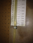
IMG_2508
Tested every 20 kts from 40 Kts to 180 Kts. Here's 60 Kts on the manometer (actually a bit less)
Date: 02/28/2012
Views: 5363
|
|
|
|
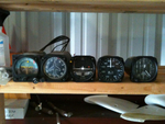
IMG_2125
These 8 lbs of instruments were removed from the old panel along with the approximately 35 lbs of Garmin H/W.
Date: 11/24/2011
Views: 5362
|
|
|
IMG_2490
Altimeter has been installed. Added a USB port for the GRT Sport. Began the label process.
Date: 11/22/2011
Views: 5360
|
|
|
|
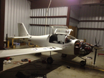
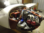
IMG_2538
Uncowled engine open for inspection of all the wiring and plumbing and physical connections.
Date: 03/02/2012
Views: 5357
|
|
|
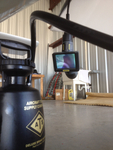
IMG_2582
Brought the pitot/static manometer out to test the P/S system.
Date: 02/27/2012
Views: 5353
|
|