|
|
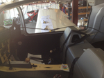
IMG_2571
The nasty job of bleeding brakes. How do you do it without assistance? You get out the inspection camera and point the camera head at the brake reservoir.
Date: 03/12/2012
Views: 3642
|
|
|
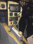
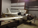
IMG_2065
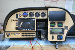
The GRT Sport has arrived and almost all the instruments have been set in their panels. This is a test fit. It was necessary to adjust the big opening in the main for clearance of some of the various instruments.
Date: 11/05/2011
Views: 5469
|
|
|
|
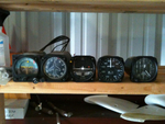
IMG_2125
These 8 lbs of instruments were removed from the old panel along with the approximately 35 lbs of Garmin H/W.
Date: 11/24/2011
Views: 3185
|
|
|
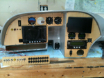
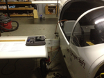
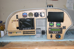
IMG_2501
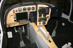
The full panel. Instrument final fit.
Date: 11/23/2011
Views: 4069
|
|
|
|
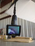
IMG_2559
Add the 2 meter extension to the 1 meter length and run the viewer down to the brake area.
Date: 03/12/2012
Views: 3766
|
|
|
IMG_2565
You can see the bubbles of air coming from the brake line as you push fluid in from below. You can also manipulate the brake master to assist the flow of air out of the system.
Date: 03/12/2012
Views: 5219
|
|
|
|
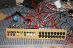
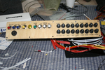
IMG_2468
Wiring begins in earnest. Color coding has been added to the switches. Red-Master, Blue-Ignition, Yellow-Starter, Green-Boost Pump & White-Lighting.
Date: 11/13/2011
Views: 3390
|
|
|
IMG_2582
Brought the pitot/static manometer out to test the P/S system.
Date: 02/27/2012
Views: 2956
|
|
|
|
IMG_2517
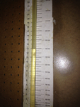
This is 160 Kts on the manometer (right on)
Date: 02/28/2012
Views: 3027
|
|
|
IMG_2551
Today I installed the new cover for the console and began work on the brake plumbing. I need to replace the line from the reservoir to the master as it interferes with the trim switch. Replacement parts now on order.
Date: 02/21/2012
Views: 2702
|
|
|
|
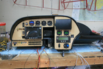
IMG_2502
Just the instruments. The wiring of everything in back will be the next big project.
Date: 11/23/2011
Views: 2996
|
|
|
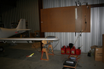
IMG_2490
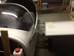
2012 Annual Condition Inspection. Opened it up and pulled the wings.
Date: 02/24/2012
Views: 2622
|
|
|
|
IMG_2537
Here you can see the numerous check lists used in the inspections laid out on the wing.
Date: 03/02/2012
Views: 3248
|
|
|
IMG_2498
Switches and breakers have been labeled.
Date: 11/22/2011
Views: 3180
|
|
|
|
IMG_2463
Here's why the bottom breakers are upside down. It puts the buss bars connecting the inputs together. The first breaker in the bottom row is the main output from the alternator so it is right side up so the output goes to the buss bars.
Date: 10/28/2011
Views: 4127
|
|
|
IMG_2454
I had some maple veneer from another project which came in handy to cover the sheet aluminum plates. I think it's much more attractive than painted aluminum.
Date: 10/24/2011
Views: 3675
|
|
|
|
IMG_2491
Other wing. I'll only show a few of the pics from the annual.
Date: 02/24/2012
Views: 3006
|
|
|
IMG_2470
Another test fit. Getting better. Still waiting on the electroluminescent light ring for the altimeter.
Date: 11/13/2011
Views: 3218
|
|
|
|
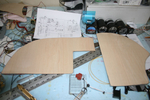
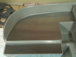
IMG_2313
Panel plates were cut from aluminum and fitted to the fiberglass.
Date: 10/06/2011
Views: 5047
|
|
|
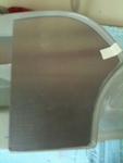
IMG_2312
This was the more difficult fit of the three.
Date: 10/06/2011
Views: 6897
|
|