|
|
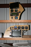
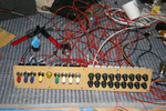
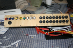
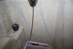
IMG_2525
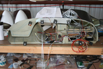
Wiring in the instrument panel. From a couple weeks ago, not the final iteration.
Date: 01/14/2012
Views: 2908
|
|
|
IMG_2522
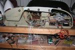
Spent several weeks identifying and relabeling aircraft wiring. Talk about tedious...
Date: 01/03/2012
Views: 2956
|
|
|
|
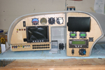
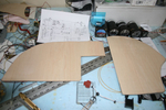
IMG_2512
Did numerous test fit insertions of the instrument panel shell. I think I finally have it ready to install.
Date: 12/16/2011
Views: 3267
|
|
|
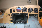
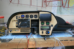
IMG_2523
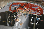
But I'm still piddling around with the wiring and cabling. Found out today that the GRT Sport SX will control a Garmin SL30 radio and the Microair 760 will support SL30 type input/output. So, I'm working on adding the necessary wiring between the two.
Date: 01/03/2012
Views: 2847
|
|
|
|
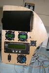
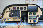
IMG_2524
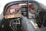
Maybe by the end of the week I can have the shell installed and wired into the aircraft so I can plug these into it. We'll see. These 26ºF (-3.3ºC) mornings have been limiting me to only 4 or 5 hours of afternoon work a day.
Date: 01/03/2012
Views: 3181
|
|
|
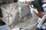
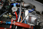
IMG_2513
Had to make up a new cover plate for the back of the transmission where alternator #2 formerly resided.
Date: 12/16/2011
Views: 2829
|
|
|
|
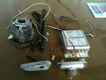
IMG_2123
And then another 7 lbs of alternator H/W and about 4 lbs of Whelen strobe/lights/power supply. That sleek piece in the lower left is one of the 6 oz AEROLED Nav/Strobe units replacing the Whelens.
Date: 11/24/2011
Views: 3164
|
|
|
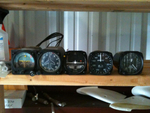
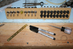
IMG_2125
These 8 lbs of instruments were removed from the old panel along with the approximately 35 lbs of Garmin H/W.
Date: 11/24/2011
Views: 3157
|
|
|
|
IMG_2468
Wiring begins in earnest. Color coding has been added to the switches. Red-Master, Blue-Ignition, Yellow-Starter, Green-Boost Pump & White-Lighting.
Date: 11/13/2011
Views: 3363
|
|
|
IMG_2470
Another test fit. Getting better. Still waiting on the electroluminescent light ring for the altimeter.
Date: 11/13/2011
Views: 3184
|
|
|
|
IMG_2490
Altimeter has been installed. Added a USB port for the GRT Sport. Began the label process.
Date: 11/22/2011
Views: 3278
|
|
|
IMG_2495
496 Mount, Microair Comm & Xponder, GRT EIS 4000, Fuel Pressure, Prop Controls.
Date: 11/22/2011
Views: 3379
|
|
|
|
IMG_2498
Switches and breakers have been labeled.
Date: 11/22/2011
Views: 3151
|
|
|
IMG_2501
The full panel. Instrument final fit.
Date: 11/23/2011
Views: 4041
|
|
|
|
IMG_2502
Just the instruments. The wiring of everything in back will be the next big project.
Date: 11/23/2011
Views: 2968
|
|
|
IMG_2437
Eventually, the 2nd alternator and supporting H/W will go. Also, I have Parahelion copper-clad aluminum fat wire which will replace the existing fat wire.
Date: 10/15/2011
Views: 3090
|
|
|
|
IMG_2456
Drilling for the rivets to hold the anchor nuts required novel technique. Eventually, all anchor nuts were installed.
Date: 10/25/2011
Views: 3929
|
|
|
IMG_2454
I had some maple veneer from another project which came in handy to cover the sheet aluminum plates. I think it's much more attractive than painted aluminum.
Date: 10/24/2011
Views: 3644
|
|
|
|
IMG_2462
Here is the switch & breaker panel all nicely assembled. Don't know if you can tell, but the bottom row of breakers (except for the first one) are all upside down.
Date: 10/28/2011
Views: 3733
|
|
|
IMG_2463
Here's why the bottom breakers are upside down. It puts the buss bars connecting the inputs together. The first breaker in the bottom row is the main output from the alternator so it is right side up so the output goes to the buss bars.
Date: 10/28/2011
Views: 4095
|
|