With the instrument module fitted, Alan fabricated a thin Aluminium bracket, then inserted the bottom half of the connector, (female pins), to the bulkhead mounted half of the connector, (mounted on the instrument module), and marked the location of the holes.
After the holes were drilled, packaging tape was applied to the fuse and the Aluminium bracket was JB KWIKed to the fuse aligning the holes to the instrument module half of the connector.
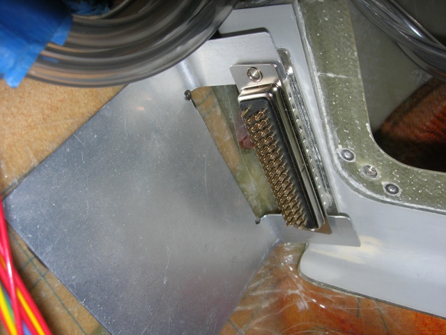
Once the JB cured, the instrument module was removed and a temporary connector, (with male pins), was screwed to the bracket with flat head screws to allow connecting and dressing wires.
See next pict.
This connector you see inserted is a solder type connector just being used for this pict. A crimp style machined connector will be used when wiring.
Y11-01-01


