Trying to wire stick grip to control Airmaster electric constant prop manual control (jog to course or fine) we came to realization we are one wire short on connector.
Thus it would save a lot of time and effort if I could use Tri State Logic for a solution.
I could easily have one wire with three states using my SPTT switch on stick.
1) Infinite resistance (not connected to anything) when switch is in neutral
2)+12V when pushing momentary switch forward
3) (-) ground when pushing momentary switch back
My goals:
** Have 2) +12V energize a 5 amp relay which runs prop Course
** Have 3) (-) energize a 5 amp relay which runs prop Fine
** Have 1) NOT energize either Course or Fine relay
Any help and or ideas greatly appreciated.
I think I would rather use relays compared to solid state because I just don't know what is going on inside the constant speed controller, and relay contacts can easily replicate resistance compared to supplied switch.
I am OK with failure mode of circuit and relays because I plan to replicate for each stick (2).
Ron Parigoris
Ron;
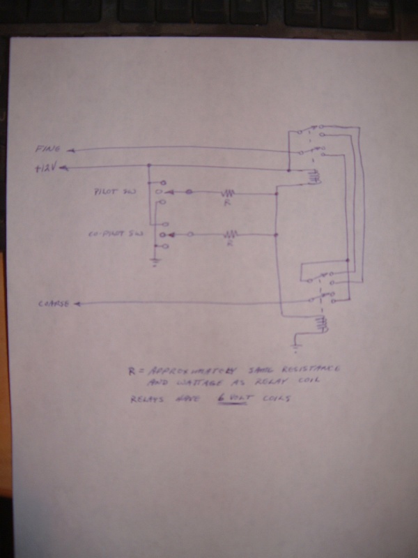
Attached is a circuit which is not particularly elegant will function as you've requested. I'm not certain that the possible failure modes are acceptable, or that you'd be happy with the relays constantly energized which is the way this circuit operates, but for what it's worth here it is. Sketch is shown with power disconnected, relays in relaxed (off) position. This circuit will connect the fine and coarse wires to each other during normal flight operation. If this is not acceptable then a diode could be introduced in each of these wires to isolate them from each other.
<![if !supportLists]>? <![endif]>With the stick switch in centre – no connection – (Situation 1) both relays are energized and no power can flow to either coarse or fine output wire.
<![if !supportLists]>? <![endif]>With stick switch supplying +12V – (Situation 2) - Upper relay has +12 on both ends of coil, therefore turns off and lower relay supplies +12V to “coarse†wire.
<![if !supportLists]>? <![endif]>With stick switch supplying ground – (situation 3) - Lower relay has both sides of coil grounded therefore turns off and upper relay supplies +12V to “fine†wire.
Resistors should be approximately the same resistance and wattage as the relay coils. You require a resistor in the lead from each stick switch so that in a situation where one stick is selecting coarse and the other fine, the resistors dissipate the energy which would otherwise be a dead short through the grip switches. In this scenario, theoretically the relay common point would remain at 6 Volts and no pitch change would happen. You could also incorporate a panel switch into this circuit, wired the same way. Note also the relays have 6 Volt coils.


