|
|
IMG_2454
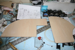
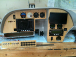
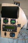
I had some maple veneer from another project which came in handy to cover the sheet aluminum plates. I think it's much more attractive than painted aluminum.
Date: 10/24/2011
Views: 5468
|
|
|
IMG_2462
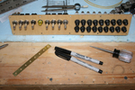
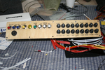
Here is the switch & breaker panel all nicely assembled. Don't know if you can tell, but the bottom row of breakers (except for the first one) are all upside down.
Date: 10/28/2011
Views: 5797
|
|
|
IMG_2463
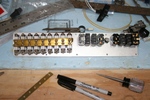
Here's why the bottom breakers are upside down. It puts the buss bars connecting the inputs together. The first breaker in the bottom row is the main output from the alternator so it is right side up so the output goes to the buss bars.
Date: 10/28/2011
Views: 6132
|
|
|
IMG_2065
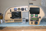
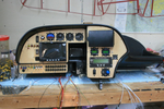
The GRT Sport has arrived and almost all the instruments have been set in their panels. This is a test fit. It was necessary to adjust the big opening in the main for clearance of some of the various instruments.
Date: 11/05/2011
Views: 8085
|
|
|
IMG_2468
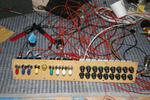
Wiring begins in earnest. Color coding has been added to the switches. Red-Master, Blue-Ignition, Yellow-Starter, Green-Boost Pump & White-Lighting.
Date: 11/13/2011
Views: 5335
|
|
|
IMG_2470
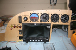
Another test fit. Getting better. Still waiting on the electroluminescent light ring for the altimeter.
Date: 11/13/2011
Views: 5315
|
|
|
IMG_2490
Altimeter has been installed. Added a USB port for the GRT Sport. Began the label process.
Date: 11/22/2011
Views: 5336
|
|
|
IMG_2495
496 Mount, Microair Comm & Xponder, GRT EIS 4000, Fuel Pressure, Prop Controls.
Date: 11/22/2011
Views: 5307
|
|
|
IMG_2498
Switches and breakers have been labeled.
Date: 11/22/2011
Views: 5325
|
|
|
IMG_2501
The full panel. Instrument final fit.
Date: 11/23/2011
Views: 6718
|
