|
|
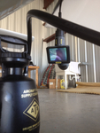
IMG_2582
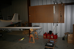
Brought the pitot/static manometer out to test the P/S system.
Date: 02/27/2012
Views: 2878
|
|
|
IMG_2447
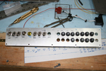
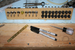
Started to make up the switch and breaker panel.
Date: 10/24/2011
Views: 4751
|
|
|
|
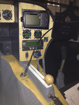
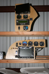
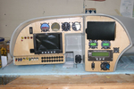
IMG_2495
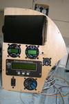
496 Mount, Microair Comm & Xponder, GRT EIS 4000, Fuel Pressure, Prop Controls.
Date: 11/22/2011
Views: 3318
|
|
|
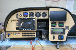
IMG_2490
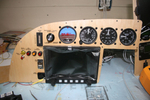
Altimeter has been installed. Added a USB port for the GRT Sport. Began the label process.
Date: 11/22/2011
Views: 3225
|
|
|
|
IMG_2462
Here is the switch & breaker panel all nicely assembled. Don't know if you can tell, but the bottom row of breakers (except for the first one) are all upside down.
Date: 10/28/2011
Views: 3665
|
|
|
IMG_2537
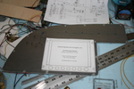
Here you can see the numerous check lists used in the inspections laid out on the wing.
Date: 03/02/2012
Views: 3168
|
|
|
|
IMG_2451
Templates were used to transfer the instrument locations to the aluminum panels for cutting.
Date: 10/24/2011
Views: 4346
|
|
|
IMG_2309
The obvious place to begin weight reduction was the ridiculously heavy instrument panel. Removed it and put the Garmin radios, etc. up for sale. Meanwhile, I began to lay out the instrument configuration in the old panel.
Date: 10/06/2011
Views: 5944
|
|
|
|
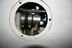
IMG_2571
The nasty job of bleeding brakes. How do you do it without assistance? You get out the inspection camera and point the camera head at the brake reservoir.
Date: 03/12/2012
Views: 3544
|
|
|
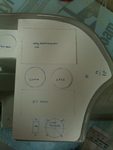
IMG_2307
Cardboard cutouts and templates were used to shape and size the panels and to decide where instruments should go.
Date: 10/06/2011
Views: 4055
|
|
|
|
IMG_2065
The GRT Sport has arrived and almost all the instruments have been set in their panels. This is a test fit. It was necessary to adjust the big opening in the main for clearance of some of the various instruments.
Date: 11/05/2011
Views: 5334
|
|
|
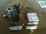
IMG_2123
And then another 7 lbs of alternator H/W and about 4 lbs of Whelen strobe/lights/power supply. That sleek piece in the lower left is one of the 6 oz AEROLED Nav/Strobe units replacing the Whelens.
Date: 11/24/2011
Views: 3104
|
|
|
|
IMG_2555
Now you can observe the reservoir from below the aircraft where you control the run of fluid into the brake.
Date: 03/12/2012
Views: 3332
|
|
|
IMG_2524
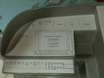
Maybe by the end of the week I can have the shell installed and wired into the aircraft so I can plug these into it. We'll see. These 26ºF (-3.3ºC) mornings have been limiting me to only 4 or 5 hours of afternoon work a day.
Date: 01/03/2012
Views: 3137
|
|
|
|
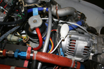
IMG_2437
Eventually, the 2nd alternator and supporting H/W will go. Also, I have Parahelion copper-clad aluminum fat wire which will replace the existing fat wire.
Date: 10/15/2011
Views: 3022
|
|
|
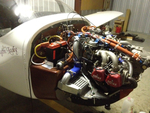
IMG_2538
Uncowled engine open for inspection of all the wiring and plumbing and physical connections.
Date: 03/02/2012
Views: 3229
|
|
|
|
IMG_2470
Another test fit. Getting better. Still waiting on the electroluminescent light ring for the altimeter.
Date: 11/13/2011
Views: 3136
|
|
|
IMG_2571
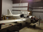
Opened all the inspection holes to ensure all is well inside.
Date: 02/24/2012
Views: 3044
|
|
|
|
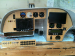
IMG_2502
Just the instruments. The wiring of everything in back will be the next big project.
Date: 11/23/2011
Views: 2909
|
|
|
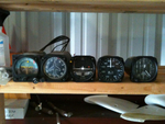
IMG_2125
These 8 lbs of instruments were removed from the old panel along with the approximately 35 lbs of Garmin H/W.
Date: 11/24/2011
Views: 3097
|
|